Using the Map View
As you discover devices on your network, WhatsUp Gold creates a map of the initial discovery device group. You can configure this map, or create other device groups and configure maps for these groups as you see fit. Regardless of the groups for which you configure maps, you can configure all maps in a variety of ways:
- Organize devices into user-specified groups, for example, all HTTP servers.
- Customize individual device icons such as workstations, containers, routers, and bridges.
- Indicate relationships among devices by using annotation objects such as rectangles, ellipses, text, network clouds, and "attached" or "free" lines.
- Show status of network link lines.
Map View is accessed on the Devices tab under View > Map View.
Interpreting the Map View
The Map View consists of device icons, annotations, and graphical indicators which are used to represent the state of your network. The device icon is a graphical representation of the device and provides the hostname or IP address of the device. The device icon can be modified adding annotations, which you can add manually, and by graphical indicators which are automatically applied to device icons.
Annotations
Annotations are graphical objects that let you customize and visually organize a map view. You can use these annotations to draw connections between devices, add images and backgrounds, provide textual information, and add visual enhancements to the Map View. Available WhatsUp Gold map annotations include:
- Circles
- Lines
- Rectangles
- Text
- Network clouds
- Polygons
- Images
The Annotation toolbar is located at the top middle of the WhatsUp Gold console Map View.
![]()
Use this toolbar to add annotations and manipulate their properties, such as border width and color.
For more information about annotations, see Adding annotations to a map.
Graphical Indicators
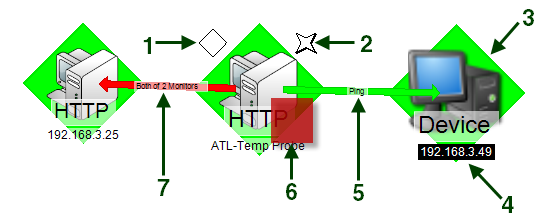
While annotations are added manually, graphical indicators are automatically applied to the device icon by WhatsUp Gold in response to state changes, or to dependencies between devices. The following diagram illustrates graphical indicators as they appear on a device icon in the Map View.

- Passive monitor indicator. A diamond shape at the upper left of the device icon, displays the state of the passive monitors associated with the device.
- SNMP indicator. A four pointed star located at the upper right of the device icon, is present when the device has SNMP credentials stored in the Credentials Library.
Note: The presence of the SNMP indicator does not indicate that SNMP is enabled on the device, or that the device is reporting SNMP traps to WhatsUp Gold.
- Device state indicator. The background color and shape directly behind the device icon, provides an indication of the state of the device as determined by the active monitors monitoring the device.
- Device status change indicator. A reverse of the normal background and foreground, indicates that the device has undergone a state change that has not yet been acknowledged.
- Up dependency indicator. A green arrow that originates at the dependent device and terminates at the device on which it dependent. The active monitors on which the device is dependent are displayed on the arrow.
- Active monitor indicator. A square located at the lower right of the device icon, indicates the state of the active monitors associated with the device. If the indicator is green, there is a recent Up state change in an active monitor. If the indicator is red, there is a recent Down state change in an active monitor.
- Down dependency indicator. A red arrow that originates at the dependent device and terminates at the device on which it dependent. The active monitors on which the device is dependent are displayed on the arrow.